Making a Macchi: Paint, landing gear and the rest

The finished model – decals made all the difference in this build.

It was painting time for my C.202, and I like to add the windscreen and any other fixed clear parts before painting so I can ensure there are no seams to fill after painting. It also protects the gunsight reflector. I dipped the windscreen and the hinged-to-the-side canopy in Future for additional clarity and, once they were dry, added the windscreen to the fuselage with white glue. Once the windscreen was dry, I attempted to mask it with Parafilm M, my usual approach. Then, disaster – my ham-handed attempt to apply the Parafilm knocked the windscreen off, which knocked the gunsight reflector off. Oof! I fixed the gunsight reflector, then re-attached the windscreen with CA glue – then bought a set of pre-cut masks from Eduard! These went on with zero drama.

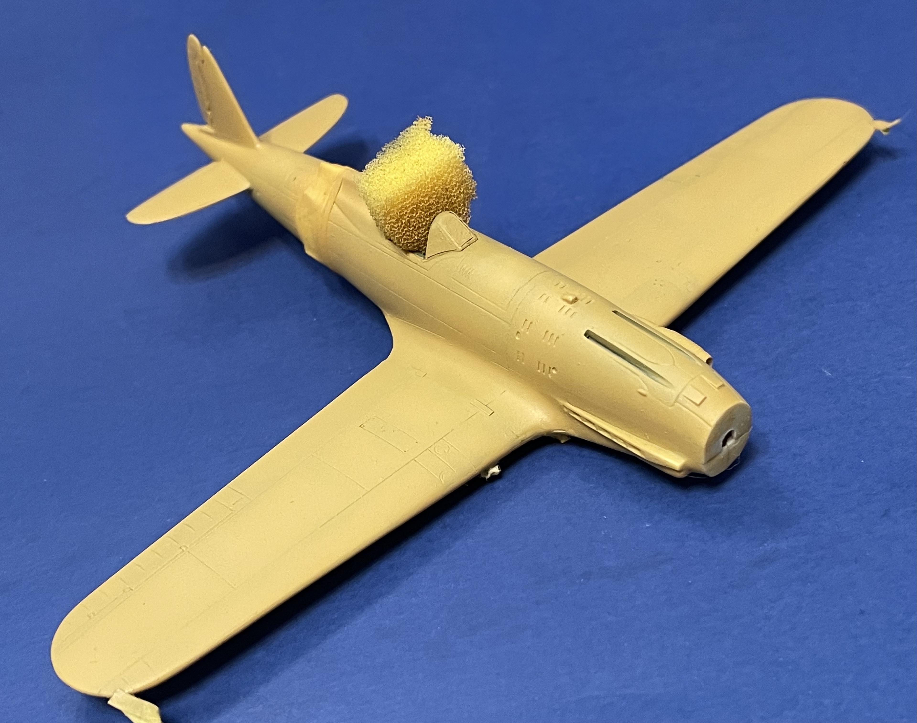
The wing tip lights were masked with bits of tape and I used wet tissue paper to mask the wheel well detail before painting. Since my old standby paints – Testers ModelMaster – were now unavailable, I decided to try out a new enamel line, True North. They had the colors I needed – FS 30266, flat Africa yellow, which matched the Italian color Nicciola Chiaro 4, and FS 36307, flat light sea gray, which matched Grigio Azzuro Chiaro 1. I also bought flat white, satin black and some colors for other projects while I was at it. 

Before I applied the camouflage colors, I pre-shaded the panel lines with Floquil engine black. I’m not a big fan of this practice, but I thought I could make it work with the relatively light color of the base camouflage. Next, I loaded up some of the True North flat white in my airbrush and painted the white band around the fuselage; I found it thinned just like ModelMaster and covered very well. I also painted the spinner, and the tips of the propeller as a base for the yellow – and then, while I was at it, painted eight more propellers from three other kits. I don’t like to waste paint, and this is a nice way to make use of it while giving yourself a gift in the future. All the propellers then had their tips airbrushed yellow, and once dry a scale four inches of the tips were masked and I painted the blades with True North satin black. This went on nicely, but it takes about 10 hours to dry thoroughly – take care in touching them until they’re all dry! The next day, I took of the masking and had 29 perfectly masked prop tips, including three on the Macchi’s propeller. 

True North’s flat Africa yellow looks very thick in the bottle, so I thinned it a bit more than usual. That was a mistake – my first batch was too thin. Adding thinner at a 3:1 ratio allowed it to spray very nicely, but it was still a bit translucent. That wasn’t really a problem – I sprayed it over the pre-shading and could build up the color until the pre-shading was nearly invisible, which was just the effect I wanted. I made sure I painted the leading edge of the lower wing and horizontal stabilizers – as if this scheme wasn’t difficult enough, the camouflage wrapped around the leading edge of the wing. It also wrapped around the nose and the tail aft of the wing. 

True North’s flat Africa mustard goes on a little translucent but looks the part.

I masked the nose, the lower wing leading edge and the rear fuselage with Tamiya yellow tape. The leading edges of the horizontal stabilizers were masked with Tamiya tape or curves. The True North light sea gray behaved similarly to the flat Africa yellow, although it was much more opaque. After a few minutes, the masking came off – there were no issues that required touch-ups.

Note the wrap-around on the ;eating edges of the wing and tail.

Now for the rest of the camouflage. Each of the three factories that made the C.202 had its own camouflage pattern – Breda with a “snake squiggle,” SAI with its “little hearts,” and Aer Machhi with its “smoke rings.” Since my plane was made by Aer Macchi, I was faced with the dreaded smoke rings – but some years ago, I’d purchased decals from Mike Grant that provided these Verde Olive Scuro (dark olive green) blotches with soft edges, a solution that would certainly be easier than trying to airbrush them in 1:72

While some cranks referred to these decals as “the end of the hobby” when they were released, decaling your entire model is not easy. First, you need to get a very good gloss coat or your model will be a silvered mess. I applied two coats of Future to the model with a broad brush. Next, I checked with my photos – although the factory applied the smoke rings at random, I was building a specific plane, so I wanted my camouflage to reflect the real plane as closely as possible. I replicated the pattern that was visible in the photos, then used the existing pattern to fill in the blanks. Over the course of two days, the model was covered in smoke ring camouflage – a grand total of 106 smoke rings. The ALPS-printed decals snuggled down well, but the ink is a bit fragile – handing it can wear it away and force you to make repairs.

Oh no! I killed the hobby!

Next came the markings for “Dai Banana!” These came from a Sky Decals sheet. I started with the Stormo logo and first-layer deals – a white version of “Dai Banana” for the nose and the Savoy Cross on the tail. The crosses on the sheet were notably oversized, so I carefully cut them down before applying them. Later, I applied the yellow “Dai Banana!” to the nose and added the crest of the House of Savoy to the cross, then added the data plates, fascist badges and wing insignia, and finally the squadron and aircraft numbers. I also added the Aer Macchi decals to the propeller. 

All the decals in place – including the cut-down cross of Savoy on the tail.

The main danger here was silvering. I spent considerable effort hunting down any areas that displayed any silvering and pierced the decals before applying more SuperSol. When that didn’t work, I went with diluted Solvaset, followed by full-strength Solvaset. That worked, eventually. A second coat of Future was brushed on in advance of a watercolor “sludge wash” made with dishwashing liquid and Payne’s gray paint. 

The wash was especially effective on the underside of the plane.

Once the wash looked right, I applied a coat of Testors Dullcote, thinned 1:1 with lacquer thinner, to kill off the shine. This seemed like a good time to paint the exhaust stacks; I brushed on some stainless steel paint, then drybrushed a shade of rust, followed by darker metal, followed by a final layer of dark brown. The exhausts are the weakest part of the kit; if I were to build it again, I would take steps to integrate a set of the aftermarket resin DB601 exhausts available today.

It was time to get the model on its landing gear. I had painted the wheels earlier in the build process, and now I detailed the Mister Kit resin struts, first by removing the anti-torque scissors so they could be replaced by photoetched parts from Eduard. The struts were painted gray, with chrome silver compression struts, and the Mister Kit photoetched gear door covers were airbrushed appropriate colors. The braces connecting the struts to the gear was folded together and added to the gear doors very carefully. I added brake lines to the back of the strut wheel housing, with corresponding lines on the inside of the gear doors to match my references. The struts were plugged into the wheel wells. The fine retraction struts were carefully removed from the kit trees with a razor knife; I cleaned them up, painted them and added them to the gear.

The center gear doors were attached to linkages that featured a small pedal-like feature; as the struts came up, the wheel would catch the pedals and pull up the center doors. The linkages were available as photoetched parts, but they required careful folding and positioning to make them symmetric from side to side. Once they were in place, I added the center doors with white scenic glue.

The main gear doors were next. I added one, then the other, with white glue. The upper strut doors were next; I took great care to make sure they were aligned with each other and to the wing. The next morning, while admiring my handiwork, I saw that one gear door was noticeably lower on the strut than the other one. I carefully removed the offending gear door, and in the process knocked off the upper strut doors, then knocked off the entire other landing gear! Much consternation ensued, followed by focused work restoring the model to its previous degree of completion. 

A simple Future-based wash greatly improved the look of the photoetched gear doors.

Far simpler was the tail wheel. I had painted it early in the build process; it was simply CA-glued into place, with care taken to make sure it was aligned properly.

One of the details missing from the kit – but very visible in any profile image – was the belly-mounted Venturi used to power the electrical system. I made my own Venturi from a short length of Albion Alloys brass tubing by flaring one end using an old airbrush needle. Inserting the needle in one end of the tube, then forcing the needle into the tube by tapping it assertively against my workbench, bent the metal just enough. The Venturi was added to a styrene strip strut and it was glued to the plane’s belly just ahead of the radiator. 

The Venturi, in place ahead of the radiator.

The kit canopy had been masked and painted from the outside, but I realized that, when open, the interior would be very visible and the glossy interior frames needed to be addressed. I masked the interiors frames – vertical first, then horizontal – and sprayed them flat black in two separate sessions. The canopy was carefully mounted on the starboard sill, and a small length of .3mm nickel-silver wire, painted white, was added to simulate the retaining cord, which kept the canopy hinges from being overstressed. I also added small lengths of fine wire to each inner side of the canopy to simulate the opening handles. I touched them with scenic glue to create round ends, then painted the rods black and the bulb ends red to match my photos. 

The exhaust stain in place – subtlety is the key. Note the hard sight.

I added exhaust stains to the sides of the fuselage with pastels – a mix of dark grays and black, brushed on with a short, cut-down brush, scrubbing it into the flat coat. I used my references to ensure the pattern of the staining was consistent with reality. The Valiant Wings book showed the plane had a set of external hard sights – a bead about mid-way on the nose and a ring on a post just outside the windscreen. Scrounging through my photoetched parts, I found the ring on a post on a Reheat set intended for U.S. aircraft. I drilled holes using a No. 80 bit, then added the ring and post, taking care to keep it aligned to the windscreen. The bead was made from some .4mm metal rod, which was CA-glued into the model and then cut to length with wire cutters.

Instead of using the kit’s plastic pitot boom, I used two lengths of telescoping brass tubing from Albion Alloys of the proper size. After CA-gluing the boom into the hole in the wing, I painted the boom African mustard. 

Earlier, I had drilled a hole to accommodate the kit’s antenna mast. Now, I glued the mast in place, painted it African mustard, and started rigging the aerial, using fibers from a pair of smoke-colored panty hose. The wire “insulators” I installed early in the build served as anchoring points. Using mini-clamps and locking tweezers, I stretched the fibers around the tail post and applied a tiny bit of CA. Positioning the clamps and tweezers allowed the glue to dry without the fibers moving. When dry, the fibers were stretched to the antenna mast and secured there. The excess on each end was stretched, then cut close to the anchoring point with Unifit 90-degree cutters. The aerial leading to the fuselage was attached to the main aerial and then stretched carefully to the fuselage insulator, again using the 90-degree cutters to cut off the excess. The glue set up on the fuselage in a slightly messy way, but photos showed a fairly large insulator on the real plane. I applied a bit of scenic glue to the mounting point and hid and sloppiness; the new “insulator” was painted black. 

The wash was especially helpful in popping out detail on the air filter.

The only thing left was to add the propeller – and just like that, after almost two decades, the C.202 joined my collection of finished models! It was worth the wait – the Valiant Wings book on the Folgore was invaluable in this project. The decal camouflage and the multitude of small details made this a learning experience 20 years in the making.

The aerial in place, including the black “insulator” on the spine that obfuscates some sloppiness in the attachment.

Hand-Made, Just Like the Original: Macchi C.202 in 1:72

By Chris Bucholtz

When green fighter units deployed to the Mediterranean Theatre, the veterans told them there was only one plane they couldn’t out-turn: the Macchi C.202. A development of the C.200, the C.202 swapped a license-build DB601 for the A.82 radial that held the C.200 back. It also boasted a new wing, an enclosed cockpit, and tremendous maneuverability. Holding it back was its armament: two 12.7mm machine guns firing through the propeller arc, plus two 7.7mm guns in the wings on later aircraft. These additional guns were often removed because of the weight and maneuverability penalties they imposed. The machine also suffered from balky radios and a criminally unreliable oxygen system that led to a remarkable level of aborts.

A Macchi-built C.202 Serie X of 51 Stormo.

The C.202 was produced in an assortment of Serie, which translates roughly into production blocks: Serie I was basically a developmental run of just 23 aircraft which reached squadron service in June, 1941. From there, 14 more Serie were built, although the total of C.202s built was only 1,191, coming from Aermacchi, Breda and SAI Ambrosini. For modelers, this creates a real conundrum – you have to identify the plane you wish to build, then check features like the tailwheel fairing, armored windscreen, various bulges and vents and even the shape of the elevators.

One of the top scorers in the C.202 was Ennio Tarantola. As a youngster, he sold fruit from a pushcart in the Piazza Cavour, earning him the nickname “Banana.” He dreamed of flying and earned his license to fly at 17 after training in gliders before joining the Regia Aeronautica.

With a whopping 110 hours under his belt, Tarantola was sent to Spain to fly the CR.42 with the Condor Legion, where he achieved his first victory over a Republican I-15. After Italy joined the war, the promising pilot was selected to train on the Ju 87. On June 29, 1941, he scored a hit on destroyer HMAS Waterhen, which had to be taken under tow. The next day, his unit finished off Waterhen, but Tarantola was himself shot down and ended up in his dinghy for 18 hours. After his rescue, Tarantola decided that eight months in the Stuka was enough and he requested a transfer back to fighters.

Ennio Tarantola describes his most recent air combat next to his Macchi C.202 Serie VII. Note the victory markings under the rear arm of the Savoy cross on the rudder.

On Nov, 4, 1941, he was assigned to the Fiat G.50-equipped 151 Squadriglia, 20 Gruppo, based in Tripoli, and a month and a day later scored his second victory, an RAF P-40 Warhawk.  Later that month 20th Gruppo withdrew to Italy to re-equip with the new Macchi C.202, and they were back in combat flying from Sicily during the massive effort to knock out the island fortress of Malta. On July 1 and 4, Tarantola shot down Spitfires, and became an ace by sharing Spitfire kills with Sqaudriglia commander Capitano Furio Nicolot Doglio, The pair downed another Spitfire on July 25, but two days later Doglio was killed in combat by Canadian ace George “Buzz” Beurling, Tarantola was wounded in the same battle.

On Oct. 11, Tarantola claimed yet another Spitfire, but three days later he survived another close call when he was forced to bail out near Sicily, again being fished from the sea by a search-and-rescue flying boat. 20 Gruppo was withdrawn for rest in December and did not return to combat until May, when it moved to Sardinia. Flying from the island, Tarantola scored victories on June 28 against a P-40 and a P-38 on July 30. On August 2, the war came to Sardinia and Tarantola flew five missions against raiding American fighters that day, claiming two 14th FG P-38s and damaging an OA-10 Catalina.

After Italy surrendered, Tarantola joined the ARN and flew against allied bombers. On April 24, 1944, he was flying a Fiat G.55 against a B-24 formation over Turin when he was jumped by P-47s, which shot his plane up and forced an injured Tarantola to bail out. He burned on the legs so badly he did not fly for the rest of the war. Tarantola joined the new Italian Air Force as an instructor and then as a demonstration pilot, retiring in November 1960. Marshal Ennio Tarantola passed away in 2001 at the age of 86.

Tarantola’s  C.202s wore the exhortation “Dai Banana!” (Go Banana!) or the right side of the cowling, which was why I chose to build his aircraft from the summer of 1942. Macchi C.202 MM9066 was a Serie VII machine; internet sources say the Hasegawa kit is a Serie III aircraft. What are the differences? There aren’t many. The most notable are the wing-mounted 7.7mm Breda-SAFAT machine guns in the wings, the armored windscreen (which was included in the kit), increased armor protection in the cockpit, and an additional bulge on the cowling. The tail wheel was also slightly modified, but this would be hard to see within the tail wheel fairing.

When I started this model, none of this was known to me – that was about 20 years ago. I think I leaped into it a blissfully unaware builder. The Hasegawa kit was not without faults – the wheel wells were basically empty holes.

The Hasegawa kit also inspired much debate over the shape of the fuselage, especially the hump behind the cockpit. Mister Kit in Italy made a replacement, which also included photoetched and resin details for the cockpit and wheel wells and resin control surfaces for the tail planes. True Details also did an interior, and Eduard itself did a photoetched set. I suppose that when I started I had come across all of these items – maybe in contest raffles or at club auctions. I’m honestly not sure! But I launched into the build, painting up the True Details cockpit using the recommended green and silver colors, and finishing up the resin control panel with its integrated gunsight. This was all added to the Mister Kit fuselage halves, which then received the cowling and tropical filter from the Hasegawa kit. The wings came next; the lower wing was added, the True Details resin wheel well “spaghetti” was dropped into the center of the wheel well, and the top wing halves were cemented into place.. There were significant gaps here, which were addressed with CA glue and sanding.

And then, something happened. Maybe it was those blank wheel wells. Maybe I started obsessing about the “smoke ring” camouflage. Whatever the reason, work suddenly stopped and the Macchi took its place on the Shelf of Doom, where it sat, enduring two house moves and 19 years. Eventually a “Shelf of Doom” challenge proposed by my friend Roy Sutherland cajoled me into re-starting it.

What’s in the box? WHAT’S IN THE BOX?!? Note the tape residue on the models’ wings.

Looking in the box after almost two decades was confusing. Where did all these non-kit parts come from? Why did I stop work on the wheel wells? Where are the tail parts?  I took stock of what I had –  an extra fuselage? Painted resin cockpit parts left outside the airplane? – and started to think about what I lacked. I did remember that years ago I’d purchased a Sky Models decal sheet with the plane I wanted to build on it; some years later, I bought a sheet of smoke ring decals from Mike Grant (which, apparently, destroyed the hobby, according to some people). What did I lack? A good reference – the “In Action” book wasn’t helpful on for the wheel wells and other details. I started scouting around on the internet and spotted something familiar: Valiant Wings’ book The Macchi MC.202 Folgore: A Technical Guide. I had reviewed this for the Journal in 2015 and had it sitting on my bookshelf!  Now I was set!

First up: the model had residue from asking tape chord-wise across the wings. I think that was there to protect the detail from sanding way back when. This came off easily with an application of Goo Gone sticker lifter. (Note: never mix up Goo Gone with Goof Off. One is friendly to plastic and the other is very much not. Do not ask how I know.) Next, I revisited the wing root seams, which still had CA glue build-up on them. After almost 20 years, I was afraid the glue would be rock hard, but sanding sticks made short work of them with little disruption of the plastic surface. I re-scribed the wings and noticed that each wing had two rectangular plates at the join of the wing to the wing root at the junction of the major panels. Instead of attempting to scribe these reinforcing plates, I made some from .005 styrene and put them in place with liquid cement.

The re-scribed wings, with the reinforcements aded at the wing roots.

I cleaned up a few other joins around the wing leading edges and the cowlings.  That left the wheel wells – which were already enclosed in the wing. Detailing them was a little like a game of “Operation,” where tweezers played a critical role. I added the roofs the wells with styrene sheet, then used strip for the ribs. The tangle of wiring at the center – part of the accessory section for the engine – was painted a rust color, given a wash, and then detail painted; other hoses and wires were added where needed to extend that detail through the bay. When I’d first assembled the model, I used Mister Kit’s nice brass  rear bulkhead, but lacking photos, I added it a few millimeters away from the well opening. The Valiant Wings book showed this bulkhead to be flush with the opening, so I used the Eduard part and aligned it properly, The Mister Kit part is now entombed inside the wheel well, never to be seen again.

The wheel wells after detailing (but before a flat coat was added).

Next, I added the engine bearers and the parts attached to them with Albion telescoping brass tubing. This was a “two steps forward/one step back” operation, with items getting knocked loose and being repaired constantly, not unlike the real item! When the bearers were in place, I’d gone as far as I could – the next details would require the mounting of the gear doors and would come during final assembly.

The next major assembly I thought to add was the radiator and oil cooler. Both of these betrayed the kit’s age – although the parts had fences inside them to prevent a “see-through” effect, there was no attempt to replicate the radiator or oil cooler screens. Research showed the to be complex areas, especially the radiator. Front and back, the radiators had “X”-shaped reinforcing rods, and a set of braces stabilized the radiator “doghouse” structure.

The radiator and oil cooler with added mesh and metal rod detail.

I used sections of wire mesh coffee filter material to replicate the screens in the radiator and oil cooler, then the radiator received sections of .01mm metal rod to replicate the radiator reinforcements. A small founded fairing immediately ahead of the radiator intake was fashioned by shaping the end of a piece of .040 half-round styrene, then snipping it off and CA-gluing it to the model. The radiator and oil cooler interiors were painted and added to the model, and then the bracing for the radiator doghouse was added using small lengths of .005 styrene sheet. The exterior of the doghouse also had some visible external latch details absent from the kit; I made these from .005 styrene and added them with liquid cement.

A view o the radiator from the front, showing the bracing made from .005 styrene and the half-dome fairing fashioned from .40 half-round stock.

The kit had no position lights on the wingtips, so I cut a notch into each side and found some clear styrene sprue, which I sanded flat on one side. Using a No. 80 drill bit, I made tiny holes in the clear styrene, then painted the styrene aluminum and then forced some Tamiya clear red and clear green into the holes. The painted clear styrene was CA-glued into the notched, with care taken to center the colored “bulbs” (remember – left is red, right is green!). The bulbs also needed to be oriented to where they were mounted in the wingtip in the real plane. Then it was merely a matter of sanding away everything that wasn’t a position light. When the contours were about right, I started polishing them with fine grades of sanding sticks and finally with Blue Magic auto polish. Once they were clear, I rescribed the area.

The left wing tip, with the finished position light in place.

The gunsight was missing its reflector, so I made one from a bit of window envelope cellophane. After carefully cutting it to shape, I ran the edges across a Sharpie pen. This gives it a black frame and also makes it much easier to see and work with! The reflector glass in the C.202 was raised on a pair of rods; I made this from a modified bit of 1:700 ship photoetched metal, and the gunsight was glued in position. To protect the reflector, I added the windscreen from the kit; this had been dipped in Future floor polish, making it possible to use CA glue to put it in place without fogging.

The gunsight reflector glass in place before the addition of the windscreen.

For once, I remembered to add the aerial mounting points before the model was painted and decalled. The tail was tough – it’s very narrow, so it was hard to drill a hole to accept a metal rod. After a couple of attempts and some remedial surgery, I managed to drill a centered hole. A tiny bit of .1mm rod was inserted and cut off close to the tail. A similar hole was drilled – with much less hassle – on the rear fuselage at the aft of the “hump” and a metal insulator was CA-glued into place and cut off. These make rigging the aerial much easier.

The two insulators for the aerial, already in place. The aerial wire will run from the tail to a mast antenna, with a lead running to the fuselage.

The resin tail components were added next. I needed to open up the mounting holes for the resin horizontal stabilizers, because they were slightly flashed over on the Mister Kit fuselage. I CA-glued the stabilizers into the fuselage, checking for alignment with the wings. Once dry, I carefully added the elevators; the base of one unit needed a .005 shim to fit properly. Again, care was taken to get the elevators dropped at the same angle to preserve alignment.

The rudder came next. It too needed a shim at the bottom to give it the correct height. The resin rudder was also thinner than the plastic vertical stabilizer, so I carefully sanded the plastic tail to thin down its trailing edge. The rudder was sanded a bit to get a good fit, then added slightly deflected to port.

Since the Mister Kit fuselage was missing the fuel filler port on the fuselage hump, I added my own. I drilled a depression into the hump, using my references to position it correctly. The filler cap is a slice of .020 styrene rod, glued in place appropriately.

Fuel filler, with tiny little cap. The answer to the question, “why didn’t the C.202’s canopy slide back?”

At this point, the model was ready for paint. We’ll see how that goes in part two of our story!