Fairey Gannet AEW.3 Part 6: The finish, and the finish

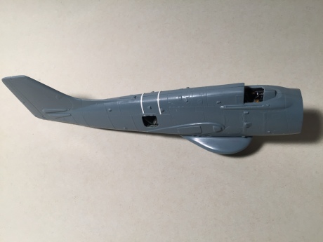
When last we left off, the Gannet AEW.3 was ready for decals. But there was a catch: the markings in the kit for XL471 are for 1977 – after the plane had stopped flying from Ark Royal. The black and white stripes on the finlet are too few in number and the B-flight marking hugs the tail leading edge where it should not. I wanted the 1975 markings from the Gannet AEW.3’s last carrier deployment. Print Scale Decals’ sheet for the Gannet includes 1975-era markings, so I used them instead.

The decals are a bit thick, but they behave themselves once they’re on the model. Decalling was nearly drama-free with the exception of some of Sword’s beautiful data markings, which desperately wanted to fold over on themselves. I used photos of XL471 to place the markings appropriately – every one of these planes was marked differently, the photos show – and discarded some of Sword’s tiniest markings because they looked like scratches in the paint instead of stencils. I also used black decal trim film to create the non-skid walkways and the deicer boots on the leading edges of the wings.

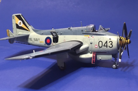
Print Scale provided the outlines of the vertical fin and finlet deicers as decals – a nice touch, if you can deal with the stress of applying these thin decals. I also added a strip of black decal to the leading edge of the vertical fin.

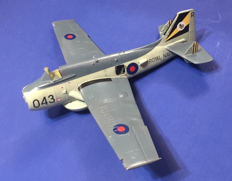
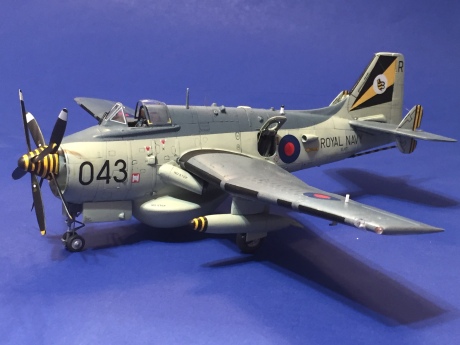
All the major markings on the model, minus the leading edge de-icers.

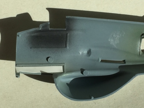
With the decals in place, I applied a fresh coat of Future and, once it was dry, gave the model a sludge-wash with a mixture of dish soap and Payne’s gray watercolor paint. When the excess wash was removed, I added some small fluid leaks using a .005 rapidograph pen. I identified areas where fluid might leak and applied a few small dots at corners of panels or behind or below hinges. Before the ink dried, I smeared it backward with my fingertip. If the effect isn’t what you want, you can remove it with water on a cotton swab and try again. The key is to not over-do it – a few leaks are one thing, but consistent leaks over the entire model would indicate a poorly-maintained aircraft and would look wrong.

I flat-coated the model with two coats of heavily-thinned Testors Dullcote, which gave the model a mostly-flat appearance but kept a bit of shine, just as a well-maintained finish would show in real life. The leading edge de-icers and walkways were sprayed with a much less thinned mixture of Dullcote to totally deaden the shine in these areas.

The propellers were painted next. A note to the personnel of the Fleet Air Arm: could you have just painted these things in a standard way? Nearly every photo I found had different colors (white or yellow) applied in different places (stripes, tips) and in different widths. I settled on a combination of yellow tips for the front propeller and broader white stripes for the rear propeller. The painted props were brushed with Future and received their small decals from the Sword sheet. Take care to mount the props in the spinners first, though – the decals should be in the same place on each blade, but without the spinners you’ll miss the fact that much of the base of the rear props is contained in the spinner. The decal goes outside of that, and then you can use the rear propeller to line up the decals on the front propeller.

I painted the spinners, the tailhook and the front of one drop tank white, followed by yellow. The single drop tank was done for a reason: in my research, I discovered that Gannet AEW.3s would often fly with one tank and pylon, on the left side, because the tank would blank out the AN/APS-20. No tanks provided the best coverage but limited endurance, so many times the planes would fly with a single tank in a counter-clockwise orbit, keeping the tank facing the inside of the orbit (and the fleet).

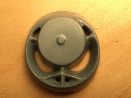
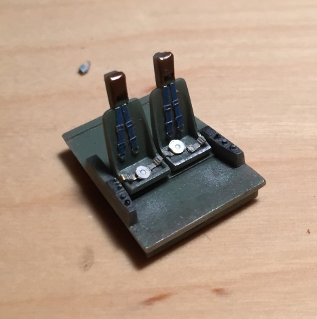
Next came the step I dreaded the most: painting the spinner stripes. The sadists in “B” Flight, who clearly hated scale modelers, applied 11 concentric yellow and black stripes to the two spinners of their Gannets. Mustering my courage, I began applying strips of cut-down Tamiya tape for curves, carefully monitoring the distance between stripes. The top of the spinner was completely masked off, since it would all be black; the black tip and last yellow stripe would be dealt with last.

After several hours of masking, I airbrushed black as lightly as possible to minimize paint creeping under the tape. After it had dried a little, I started peeling stripe after stripe and was astonished to see it had all worked out! I masked off my work and put the tip of the spinner through the appropriate sized hole in a circle template, and painted the tip (and defined the last yellow stripe at the same time). My modeling nightmare turned out not to be as bad as I’d feared! After this, the tail hook and drop tank were a breeze.

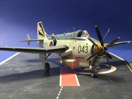
The painted spinner, with propellers. You are getting sleepy… sleepy…

The canopy came from the Sword aftermarket kit. I cut the vacuformed canopy off the carrier sheet and removed the windscreen, then dipped it in Future and allowed it to dry. Later, I masked it, painted it black and then EDSG, and added the yellow “cut here” markings from the Sword decal sheet. It received a second dip and was set aside for final assembly. The Print Scale sheet also included two very thin parallel white line decals; I used them to replicate the seals around the windscreen panels. I could measure the perimeter of each pane and cut two identical pieces, which were transferred to the windscreen and then given a coat of Future to seal them in place (decals can’t grip bare transparent plastic very well). It took 10 tiny strips to finish the windscreen. Once they were dried, I used scenic glue to install the tiny photoetched windshield wiper included on the kit’s photoetched fret.

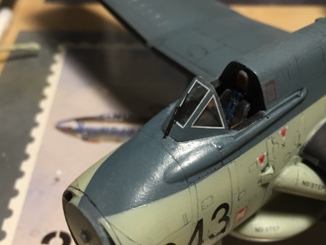
The white decal strips neatly replicated the windshield seal, and the wiper came from the kit.

Nothing from here could progress until the plane was on its landing gear. The main gear were notable for their lack of axles – there was nothing for the wheels to fit on to! I drilled holes into the main gear where the axles should be, and then used Albion Alloys tubing to make new axles – which I fit into the wheels. I found it easier to add the axles to the struts on the finished model than to slip the wheels onto the axles. The main mounts we cleaned up and I removed the anti-torque scissors with a motor tool. These were replaced by photo-etched parts from Eduard intended for the Gannet ASW.2. Photoetched brass tie-downs, painted solder brake lines, and other small details were added to the struts, which were finally outfitted with a small placard decal swiped from a Hasegawa weapons set.

One right, one left. The placards read, “if you can read this, put down my damn model!”

The nose gear was much more complex. I removed the single retraction strut and the anti-torque scissors and removed the mold lines by scraping them with a No. 11 blade. Then, I started adding bits from the Eduard set, including attachment points for the two retraction struts. These struts interfaced with the front hinges of the nose gear doors – so I had to fashion new hinges from strip styrene for the doors as well. The struts were made from two lengths of telescoping Albion Alloys brass tubing, which would allow me to adjust their lengths during final assembly. I also re-made the towing bracket on the front of the gear and added the shrink struts and other details to complete a rather complex set of landing gear.

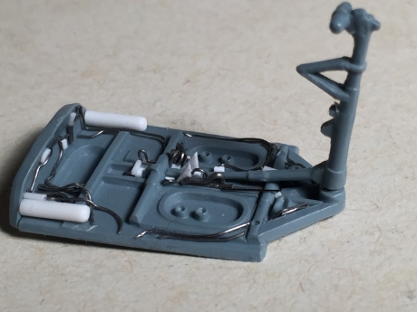
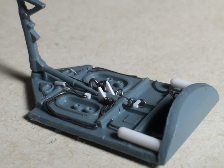
The nose gear, before the application of paint.

The nose gear plugged into a nice hole in the nose well bay, but the mains fit poorly into odd box-shaped holes on the outer sides of the wheel bays. Their retraction struts also rested on a raised ledge on the forward walls of the bays. These two things made mounting the main gear a challenge, which was only overcome by patience and careful application of CA glue.

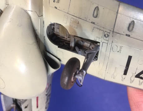
The right main gear installed, with the shrink strut added.

I painted the wheels and tires as I usually do, but I applied a lesson I learned building an Airfix M6 bomb service truck. After painting the tires an appropriate dark gray-brown, I applied pastels ranging from black to brown to them. This weathered the tires, but it also made them dead flat – exactly as worn rubber should appear. The wheels were joined to the struts – some adjustment was needed to the both nose wheels in contact with the ground – and with that the model was on its gear.

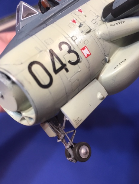
The nose wheel. with the retraction struts anchored to the door hinges.

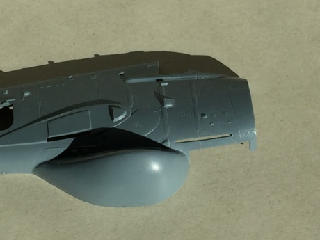
Next, the various antennas were removed from the sprues, cleaned up, and CA-glued to a popsicle stick for painting. The CA adheres well enough for painting, but the parts can still be easily detached. They were then added using photos as a guide. The pitot sensor is not called out in the instructions – it goes below the outer left wing.

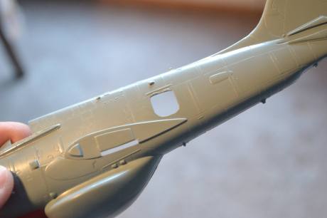
One of the sensors on the belly of the machine was revealed in photos to be a round, hollow cylinder with a tube inside of it; the kit part was much simplified, so I drilled it out and added the internal tube from a bit of solder. After it was painted and added, it’s barely visible – but it’s a neat detail!

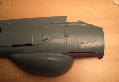
The landing light bays were painted gray and fitted with an MV lens of the proper size. A small “wire” was added from fine solder, and the covers were cut from clear packing tape. These were cut slightly oversized and adhered on their own; any overlap of the painted areas was carefully brushed with Dullcote to eliminate its shine.

Gear doors came next. The mains were butt-joined to the lower wing at the edge of the wheel wells; the nose gear doors went into place and had the nose gear retraction struts extended to the front hinges. A painless process!

The pylons and tank were added next. I had to adjust the profile of the lower edge of the pylons to allow the tank to sit at the appropriate angle; they were then CA-glued to the wings. Since there were no attachment points, I was careful to get them aligned. The tailhook went into place with no fuss at all.

I un-masked the boarding ladder recess and set about making a ladder. The ladder cover folded over to form the lower rung of the ladder; the outer side of the ladder folded up and had an extension to reach the lower rung. The cover was made from .005 styrene, while the rest of the ladder was very carefully assembled from .020 by .020 styrene. The extension was made of wire. It was painted, assembled and added to the model with a shocking lack of hassle.

The boarding ladder is a small but colorful detail and was shockingly easy to make.

The AEW.3 had two different aerial arrangements, early and late. Naturally, the late arrangement was the weirdest. The antennas were suspended between the top of the tail and antenna masts on the fuselage spine by springs mounted on the inside of the finlets. I made mounting plates for the finlets from .005 styrene and drilled holes to mount tiny lengths of .006 acupuncture needles, which would double as my springs. I also drilled a hole in the tippy top of the leading edge of the vertical fin and added a small bit of metal rod as the mast. I tweezed a fiber from a pair of black panty hose and, using CA glue, tweezers and a lot of care, strung it from post to spring to tail to spring to post.

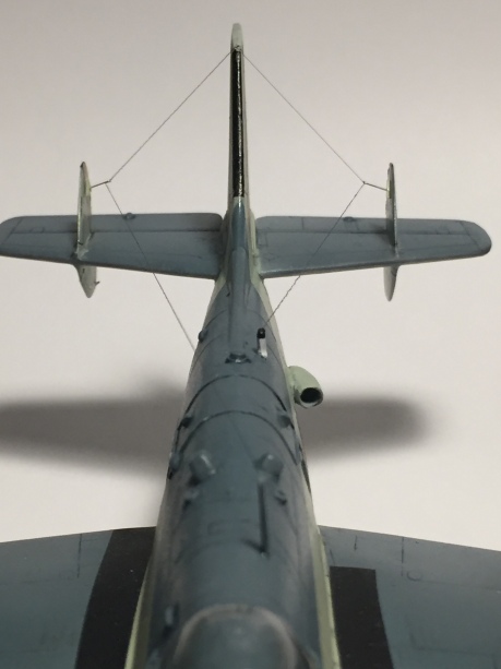
Asymmetrical installation. of UHF aerials, with the “springs” on the finlets clearly visible.

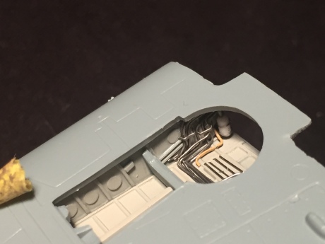
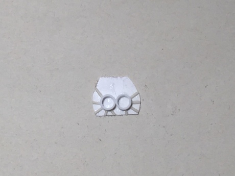
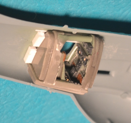
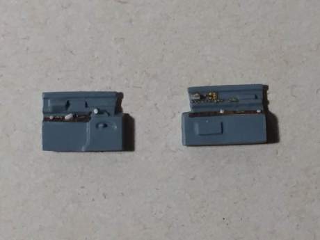
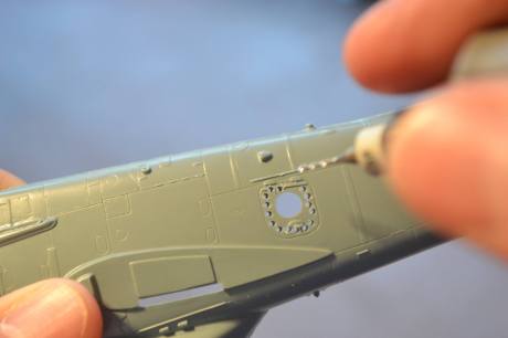
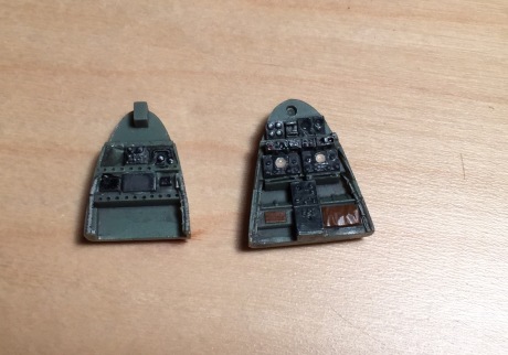
The radar observers’ doors came from the resin set for the radar compartment, but I found the interior detail lacking. It was sanded off and I replaced it with fine solder, styrene and photoetched bits. I also used Apoxy-Scuplt to mold the roll-up blinds used to blank off the windows in the daytime so the operators could see their screens; straps were made with flattened fine solder. After these were painted they were added to the top of the doors’ interiors.

The kit door windows are domed on the outside but are flat on the inside. Thoughtfully, Sword provided replacements in vacuformed plastic that are true domes inside and outside. Somehow, I managed to throw mine away after cutting the windscreen off the clear carrier and I found them only after going through my workshop trash can item by item, CSI-style. That was one problem solved. Then I had to cut these domes out and get their tiny circumferences round. Once that was done, I dropped one of them on the floor and spent 20 minutes trying to find it. Upon its location, it was immediately adhered to the window opening with Future, which sticks well and doesn’t mar clear parts.

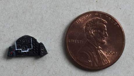
Domes on, and handles yet to come. Here, the doors have nearly been crushed by a quarter.

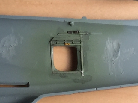
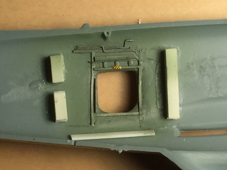
Tiny bits of .020 styrene rod were placed on the inside and outside of the doors, and photoetched handles (sourced from random bits of photoetched sheets intended for P-51Ds!) were carefully added. The doors themselves were CA-glued in place, along with a brass support rod.

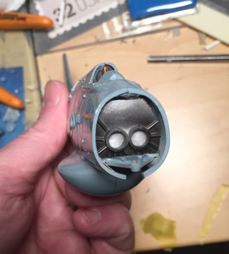
The radar observer’s compartment door, detailed and in place.

Next, I substituted .020 by .040 styrene strip for the four outer wing antenna provided in the kit as photoetched parts. I used Dullcote as the adhesive and left the plastic white to match the real items. These antennas seen to have been located strategically so future modelers could knock them off!

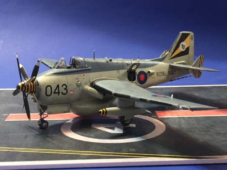
The final step was to apply that crazy propeller and spinner. And with that, it was done – what I hope is an attractive model of a rather homely airplane! I learned a lot building the Gannet AEW.3 – the Sword kit is good but leaves a lot of areas to the modeler to detail. If you have references and patience, you can fully flex your modeling skills on the AEW.3!

Fairey Gannet AEW.3 Part 5: Only Shades of Gray

When we left off on the Gannet back in January, the wings were on and we’d added the wing-tip lights and the leading-edge bays for the landing lights. In September, I finally picked the model up again (after spending time finishing a CF-100 building a Fokker Dr. I and doing a lot of work on a Firefly F.Mk. I – but these are totally different stories). Part of the delay was that I had lost the canopy/windscreen. I couldn’t find the darn thing anywhere, and an email to Sword vanished into the electronic ether with no response to be had. Months passed and I finally resigned myself to finding an alternative, the transparent part re-materialized on my desk. Perhaps I had confused it for the cockpit glass to a Firefly, or perhaps it just managed to elude my searches, but in any case I was back in business.


The first point of order was to get the horizontal tails on properly. There are no mounting points for the tails (which is weird, since the wings had them) and so their locations were suspect. It would be easy to get the horizontals too far forward or aft; studying drawings and photos was a must in placing the first one. I attached it with CA glue and had a minimal seam to address at the join. The other horizontal fit a little less well but the seam was handled with Mr. Surfacer 500. Alignment of the horizontals is a snap when the finlets are in place: hold the plane by the wing tips, looking at it from its blind spot below the tail, then rock the tail down. The winglets should touch the wings simultaneously on both sides.

Next came the windscreen. It was cut from the canopy with a cutoff wheel in a motor tool, and the trailing edge was sanded to shape and the whole thing was dipped in Future (or PFM, or whatever it’s called this week) and allowed to dry overnight under an overturned bowl for dust protection. The fit of the windscreen was pretty good, save for some minor gaps on the front left side which were eradicated with Mr. Surfacer. I masked the transparent panels with Parafilm M.


Next, I handled the jet exhausts, which were located just below the leading edges of the wings. The kit provided the exhaust shrouds in halves, with the exhausts themselves also in halves. I found the exhausts’ thickness to be all out of whack compared to photos, so I knew I’d have to make new ones. First, though, I had to get the shrouds built and installed symmetrically on the fuselage. The shrouds went together easily, with a little sanding needed at their seams and on the bottom edges to even them out, and then onto the fuselage they went. There’s an outline on the fuselage that gives a hint of where they should go. After a lot of test-fitting I went for it and CA-glued them into place; they fit with the merest of seams and Mr. Surfacer again came to the rescue.


As for the exhausts themselves, I first tried to bend brass tubing to shape. No dice – the odd semi-airfoil shape was impossible to impart on brass. Next, I tried stretching plastic rod, which was a tremendous waste of time. What could I have on hand that could fulfill the role? A visit to the kitchen’s junk drawer yielded three plastic drinking straws of various diameters. In Goldilocks style, one was too small, one was too big but the third was just right. I cut short segments to length and bent them carefully to shape, leaving them in the shrouds for several days preserve their new profiles. Then I pulled them out, airbrushed them with Testors metallizer burnt metal, and set them aside for final assembly.


Now it was time for real painting. First came black – I sprayed it over the windscreen as the interior color, and outlined the panel lines. This pre-shading in almost never really visible after the final paint job, which is just what I want. I masked the nose (to prevent paint getting into the open intakes) and prepared my first color.


Convention holds that you paint the light colors first. Convention is stupid. You paint the color that’s easiest to mask first. In this case, it was the extra dark sea gray (EDSG) on the top of the fuselage, the wings and the tail. I broke out the AeroMaster gunship gray that had served me so well with the Firefly FR.5 and applied a coat over the appropriate areas – including the wrap-around on the wing leading edge. This was important to get with the first color because of the inconvenient position of the exhaust shrouds.


Looks nice! But what is that gray?

The paint went down beautifully – but there was a problem. It didn’t really look like the color photos of Gannets in my references. Roy Sutherland said it wasn’t dark enough, and he was right. I started experimenting and came up with a formula that worked: 17 drops of ocean gray, 2 drops of dark sea blue, and 6 drops of PRU blue. The paint was sprayed on the model and worked perfectly; the model was clearly a dark gray in indoor light, but took on a blue tone in sunlight, just like the real airplane.

The right shade of EDSG makes a big difference…

Much Tamiya tape was harmed in the making of this model.

I masked the appropriate parts of the model – wings, lower leading edge, tail, and upper fuselage – with Tamiya tape. The demarcation on the fuselage was described with Tamiya’s tape for curves, which worked beautifully. Wedges of foam were placed in the radar observers’ compartment openings and the wheel wells and boarding ladder cutout were stuffed with wet tissue paper. Testors sky type S was loaded into the airbrush and I went to work on the bottom of the plane. For whatever reason, my Paasche VL would only spray a small bit of paint before stopping; repeated cleanings didn’t fix the issue. The fact that my gray shades worked wonderfully led me to the conclusion that the sky type S was causing the problem. I persisted – in fits and starts, the entire Gannet was treated to a neat coat of this weird gray-green color.


When the masking came off, the result was superb. There were five minor areas that needed touch-up: an area on one of the rudders where too much pre-shading was visible, the areas around the radar compartment doors, and the demarcation on the nose and tail on the left side. Matching the camouflage side to side can be tough, and I really fretted over getting this right. My research found two distinct demarkations on Gannet AEW.3s: one that broke down at the back of the canopy and then pinched toward the center of the nose and a second that lacked that break, continuing a straight line from where the paint curved up on the tail all the way to the pinch in the nose. The plane I was building, XL471, had the latter according to my photos.


My issue was that the EDSG wasn’t perfectly symmetric on the nose and on the tail. The right side was the least accurate, so I remasked the nose and the upward curve toward the tail and repainted. Success! All the touch-ups went without flaw and now, looking down on the model, the demarcation of the EDSG is identical from side to side.

The model was now ready for decals. But there’s a catch: the markings in the kit for XL471 are wrong. The black and white stripes on the finlet are too few in number and the B-flight marking hugs that tail leading edge where it should not. Replacements exist, but they are hard to find; there were two Model Art decal sheets with the markings, and AlleyCat’s spectacular sheet includes XL471. All of these are impossible to obtain. Fortunately, the very day of this minor crisis, Print Scale Decals’ sheet for the Gannet was released and I bought a set. I await their arrival!


Next time: decals, weathering and the landing gear.

Gannet AEW.3: Wheel Wells, Wings and Wingtip Lights

When we last left the Gannet, the fuselage was detailed and all buttoned up. That’s where she sat for a long while as I worked on the Sikorsky S-38. But, once the S-38’s fuselage was closed up, I switched back to spend some quality time with the Gannet.

OK, so I have a hard time finishing anything. At least the A-3, F-106 and Fokker Triplane aren’t visible here…

The wings and horizontal tail were the next stage. I started with the tail; the stabilizers are provided in upper and lower halves. After trimming them from the sprues and cleaning them up, I cemented the first set together – and then realized they were handed, and that I’d glued two top halves together! I pried them apart and re-glued them, feeling lucky to have caught my mistake.

Next came the finlets. I found that on each stabilizer, one finlet – the top on one, the bottom on the other – didn’t really fit well. They all required repeated filling and sanding, to be honest, and then I needed to re-scribe the finlets. Between the original Gannet AS.1 and the AEW.3, Fairey had decided to add de-icing equipment to the finlets, so scribing could not be overlooked. Photos of the real plane showed a distinct dark panel boundary between the de-icing panel and the rest of the finlet.

As I was re-scribing, I noticed that the panel detail on the horizontals was different. I dawned on me: I had caught my error, then repeated it. Twice! After much blue language (said with a British accent in order to maintain the authenticity of this build), I realized that prying the halves apart was no longer an option. Instead, I sanded the detail off the top of one stabilizer and off the bottom of the second, and re-scribed the detail to match the opposite side. This was slightly difficult with the finlets in the way, but I accomplished it and happily set the horizontals aside for later.

Before I could add the wings, I needed to detail the wheel wells. The kit provides three sides for each well and a center bulkhead; the fourth side is the side of the fuselage on this mid-wing aircraft. These parts were all added to the upper wing, and the fit was not bad. Hunting for photos was a challenge – I found images strewn all over the internet of AEW.3s in Arizona in the U.S. and Yeovilton, Newark, Yorkshire and Gatwick in the U.K.  No one set captures the entirety of both wheel wells, so some mental jigsaw puzzling was needed to figure out where details went.

Basically, the wheel wells featured a ribbed plate (smooth in the kit) that covered a circuit box. Wiring runs led up the front side of the wells and fanned out toward a bus mounted against that center bulkhead. Other hydraulic lines and some woven bundles of wiring continued along the other sides of the inner wells. The detail here varied from side to side. The outer wells, where the strut retraction mechanisms were housed, were essentially the same, but mirrored, with an assortment of struts and hydraulic lines.

The right inner well had a large blue tank for nitrogen (I believe) mounted against its front corner, with and assortment of circuit boxes placed in sequence behind it. The left inner well had some significant ducting and couplers against it. In all, it’s a very busy area. By the way, the Gannet AS.1 and AS.3 have wheel wells that are much, much less crowded – don’t make the mistake of using an AS.1 well (or, maybe, trying to use Eduard parts intended for the AS.1 or AS.3) as the template for the AEW.3’s wells!

This was a lot to replicate. I did it in steps: first I added ribs to the plate at the center of the inner wells, then started in with the wire runs. These were made with fine lead wire; with careful folding, I could get five wires that bent at the same angles. A bit of thin CA in the back of the wires held them together, and they were secured inside the wheel bays. Initially, I mis-interpreted the runs that fanned out to the bus and later realized I had bent them 180 degrees in the wrong direction! Luckily, I was able to fix my mistakes and keep going. These runs also received retaining brackets made from flattened solder. The woven wire runs were made from fine copper wire that was twisted together and cut to shape. It was added where appropriate.

With the lower wing test-fit, the detail in the left inner bay starts to come together.

Preliminary work – note the ribs on the panel and the copper cable run.

The fuselage bulkheads were the trickiest part – none of the detail added here could impinge on the detail under the wing when the wings were added. Before I added any detail, I noticed the inner walls of the bays had very visible rivets. Using a rivet tool and Dymo label tape as a guide, I added rivets to the inner walls of the wheel bays.

The inner walls of the wheel bays were riveted and detailed as appropriate. This detail had to mesh with the detail on the upper wing.

Detailing started with the nitrogen tank, which was made by sanding a nub of .040 styrene rod round at the ends, then wrapping with short lengths of flattened lead wire. Styrene “valves” were added and the whole thing was glued into the wheel well corner. Circuit boxes stolen from HO train details and other boxes cut from styrene completed the detail on the left side. The right side received the valves and hoses for the fuel system, which were made from thicker lead wire, plus three more electronics boxes made from styrene strip.

Wheel bays looking back-to-front. Note the blue nitrogen tank.

The outer bays, featuring the retratction mechanisms, were detailed with lead wire, followed by some styrene rod for the various struts, one of which stands proud above the detail above it in the bay. The whole mess was then airbrushed medium gray, followed by careful detail painting of the brownish fiberglass ribbed panels, the blue tank, the orange fuel system fittings, and a few other items. A heavy wash followed and once that was dry, I dry-brushed with a lightened shade of gray. I added a couple of square data placard with a .005 black rapidograph pen, and decided to stop there.

Wheel bays viewed front to back

The lower wings snap into slots; the top wings rest atop these. I found that my detail fit together very well, although the wings themselves needed some sanding and filling – and shimming – to attach to the fuselage and stay in alignment to the rest of the model. The panel lines I obscured on the wings were replaced, with a scribing template and a sharpened thumbtack coming in handy for the square panels with rounded corners.

Note the wing root – styrene shims and Apoxie Sculpt helped blend in the wings.


The lights on the wings were treated somewhat carelessly. The landing lights have clear covers, but there’s no bulb inside them. The position lights on the wingtips are simply not there. I sanded a notch in each wing tip, then cut pieces of clear sprue and sanded a right angle into each to fit the notch. A tiny hole was drilled into each light and clear red and green-blue paint was inserted into the holes to represent the light bulbs. The styrene was CA-glued into the notches in the wingtips and carefully sanded to the original contours, then polished to transparency. The landing light openings were cleaned up and boxed off with .050 styrene; they would be painted gray later after the model was painted, then equipped with MV lenses and covered by covers made with clear packing tape.

The left wing showing the boxed-in landing light bay and the position light. If you look closely, you can see the red “bulb.”

The wheel wells aren’t totally done – the trailing interiors of the outer bays have vertical stanchions that I’ll add only after masking and painting – but at this point the wings are on and aligned, which a pretty good step forward from where the model was art this time last year.

Next, I’ll add the tail, the windscreen and the exhausts for the turboprop engines – and then, the plane will be ready for paint!


Have you put on some weight? Building the Gannet AEW.3, part 3

The Gannet’s progress has been slow, but deliberate. When we left off, I said I was going to open the boarding ladder, which Sword outlines quite nicely on the right side of the fuselage. I almost considered not cutting it out, because it impinged on the nose wheel well, but I then realized I could simply put a piece of .005 styrene over the right upper wall of the well and it would be just fine.


Of course, I then had to cut a slit in the side of the model that was 7/10ths of an inch long and 1/32 of an inch wide. As I did with the radar observer’s compartment doors, I chain drilled the ladder opening. The difference here was I had to drill every one of the holes in a near-perfect line. My fear was that I’d end up with an overly-wide opening, which would have looked cartoonish. Instead, when I cleaned up the opening with a No. 11 blade and some sandpaper, it looked just fine. The .005 styrene was added and the bay was airbrushed red; the interior of the wheel bay was painted gray. Mission accomplished!

After chain-drilling, gentle carving and a bit of sanding, the ladder compartment is opened...

After chain-drilling, gentle carving and a bit of sanding, the ladder compartment is opened…


And, just like that, the back of the ladder compartment is closed, with .005 styrene.

And, just like that, the back of the ladder compartment is closed, with .005 styrene.

A little red paint finished off the ladder compartment.

A little red paint finished off the ladder compartment.

Next, I opened up all the intakes in the nose. There are six of them – and the nose piece is very, very thick. The lower intakes are perfectly round, so it was a simple matter of drilling them out. Photos showed these intakes had screens inside of them; I struggled to find the right parts to replicate this until I stumbled across some 1:700 modern destroyer helicopter deck safety nets, which were perfect solutions.


The main intakes took a lot of work with a motor tool to open up, followed by plenty of careful cleanup with a No.11 blade and sandpaper. Getting the shapes of the openings the same was critical; that meant the first intake went really easily and the second one took a half hour to match up. The same went for the upper intakes.

Oh, cutting this open was fun.

Oh, cutting this open was fun.

Now I had to start thinking strategically. This model was going to be a tail-sitter for sure with the resin radar observer’s position well back of the main gear. To offset that, I added some pieces of thick styrene strip to the top of the nose wheel bay to function as a dam of sorts, then loaded in about 14 grams of split shot lead fishing weights, all secured with white glue. Another piece of styrene blocked it all in place.


Then, I made the turbine faces for the Double Mamba engine. This was fairly simple. First, I made a backing plate that fit the fuselage; this would go right against the styrene strip at the front of the weight dam. Next, I added two quarter-inch sections of 7/32nds styrene tubing, gluing in place so that they were directly behind the inside walls of the intakes in relation to the nose piece. Turbine detail was added with half-round styrene strip; after it was glued into place, the excess was trimmed away.

Simple but effective (and completed in less than an hour at the Fremont Hornets' buildfest).

Simple but effective (and completed in less than an hour at the Fremont Hornets’ buildfest).

I painted this black, in keeping with photos, and lightly drybrushed my turbine blades. The goal here was not to replicate the entirety of the duct but to give a suggestion of something inside the nose, and this worked well.


Next, I joined the fuselage halves. The fit was not great, but I worked in sections to close it up. Sanding took a toll on some detail; most of it I could rescribe with my UM scribing tool, but the big reinforcement bands on the fuselage had to be replaced with strips of .005 styrene. Some small antenna detail was lost on the bottom, but this could be replaced during final construction.

All closed up and (mostly) rescribed.

Note the two white strips - detail lost in sanding was replaced with .005 styrene strips.

Note the two white strips – detail lost in sanding was replaced with .005 styrene strips.

Then, I added the turbine section. It fit neatly, and it blanked off the nose weight just behind it.

Peek a boo! The turbine section in its new home.

Peek a boo! The turbine section in its new home.

I painted the nose piece sky; this way, after it was added, I wouldn’t have to mask the black turbine section inside it during final painting. It also presented somewhat of a sloppy fit. It went on, but I had to do some significant sanding to get rid of seams and steps. That was followed by some tough rescribing of the fasteners on the nose, which I accomplished with Dymo tape and an old Verlinden scribing template. The rest of the nose detail was also added back in.


Whew! I now have a heavy but completely rescribed fuselage that’s ready for its wings. I’m going to pause, however, to work on another great 1950s design, the F-106 Delta Dart. More from the Gannet when the Delta Dart reaches the same stage the as this build!


Dammit, Gannet! Building Sword’s AEW.3, part 2

The Gannet AEW.3 build continues at a deliberate pace, with the holidays and various other things taking a bite out of my modeling time. I also paused to build this for my father-in-law’s N-gauge railroad layout as a Christmas gift:

dairy-queen

Who wants a teeny, tiny, itty-bitty, teeny-weenie, little Blizzard?


Then I was able to get back to work on the Gannet!


The floor and bulkheads were joined by the overhead duct in the Sword set to create a single radar observers’ compartment. To keep the compartment in place, I added lengths of styrene strip in one side of the fuselage. This gives a positive location for these parts and a way to ensure that they stay glued in place; nothing is more painful than having to crack open a model after a cockpit breaks loose inside a sealed fuselage!

The completed radar observers' compartment, held in place by styrene strip guides

The completed radar observers’ compartment, held in place by styrene strip guides.


The extra overhead detail panels from the Sword kit fit poorly, and I thought I could add the detail easier on my own, anyway. The extra detailing in the radar observers’ compartment was accomplished fairly quickly, because I did something I rarely do: I stopped to figure out what would actually be visible. Although I had some good photos to work from, they were taken of an aircraft with the seats and much of the radar equipment removed. Put the seats back in, and you can’t see a lot of the detail. I added some structure from styrene strip and rod, made a couple of small black boxes from styrene card and Reheat photoetched instrument faces, and gave it all a wash to pop out the detail. The final touches were the emergency egress handles above the hatch openings; these were made from bits of styrene painted yellow and glued in place. The black stripes were drawn on with a .005mm Rapidograph pen.

Let side of fuselage, with extra detail...

Let side of fuselage, with extra detail…

...And the right side. Note the small emergency egress handle above the door.

…And the right side. Note the small emergency egress handle above the door.


The next item of interest was the nose gear bay roof. The kit provides a good approximation of the basics, but omits the jungle of hydraulic and electrical wires so typical of 1950s wheel wells. Using photos, a copious amount of fine solder of three sizes, styrene bits and even a piece of stiff steel wire here and there, I added additional detail.

The strut was set in place to make sure my added detail didn't make fitting the strut impossible later.

The strut was set in place to make sure my added detail didn’t make fitting the strut impossible later.

Detail in the form of hydraulic lines added to the nose gear bay.

Detail in the form of hydraulic lines added to the nose gear bay.


Then, the whole thing was painted, given a wash and dry-brushed. And it looked great, except for the fact that I painted it the wrong color (interior gray-green). I painted over my work in the correct medium gray color and repeated the wash/dry-brushing routine. A bit of detail painting followed, and the nose wheel compartment was complete and ready to add to the model.

Why do they call it a wash? It only makes the parts look dirtier! I mean, come on!

Why do they call it a wash? It only makes the parts look dirtier! I mean, come on!

At this point, a person not suffering from AMS would glue the interior parts in, join the fuselage halves, and get on with it. Not me! Next steps (pun intended) are the boarding ladder compartment and opening up the intakes in the nose (and creating a new compressor section for the Double Mamba engine to go behind it). Stay tuned for more gruesome details!

Homely but hard-working: Sword’s Gannet AEW.3, part 1

The Fairey Gannet came in a number of variants – the AS.1 and AS.4 anti-submarine warfare platforms, the T.2 and T.5 trainer modifications, and the COD.4 trash-hauler – but if any version could be said to be the most attractive Gannet, it was the AEW.3. This is truly damning with faint praise; with its bulging radome and finlet-bedecked empennage, plus its decidedly un-aerodynamic collection of antennas, scoops and other protrusions, the AEW.3 was an odd-looking machine by any standard.

Nearly everything about the Gannet AEW.3 was different from the AS.1: the exhaust was relocated, the fuselage lost its additional seats behind the cockpit and instead housed two radar observers in a compartment submerged in the redesigned fuselage; the shape of the vertical fin was changed to offset the loss of directional stability caused by the omission of the long canopy. The landing gear was lengthened by three feet to give the radome deck clearance. The plane differed so much from the original Gannet that there was talk of renaming it the Albatross, but the Royal Navy’s retirement of the anti-submarine Gannets around the time the AEW.3 made its fleet debut in 1959 limited the possible confusion.

Built to replace the Skyraider AEW.1 (an AD-4W in U.S. Navy parlance), the Gannet AEW.3 used the same electronics – the AN/APS-20 radar system. It was intended as a stop-gap measure until a British purpose-built aircraft incorporating the latest in electronics could be built for the CVA-01 class of aircraft carriers. Unfortunately, the Defense White Paper of 1966 – the same document that cancelled the TSR.2 – put an end to Britain’s plans for a large carrier for almost 50 years, and it meant that the AEW.3 would have to soldier on with no replacement in sight. They operated right up until the last carrier they could fly from, Ark Royal, was retired in 1972, and then from land bases until 1978. In the end their two biggest enemies were attrition – 22 of the 44 built were lost to accidents – and the Shackleton program. Numerous Gannets lost their radars to Shackleton MR.2s, which rendered the Gannet airframes expendable. Only seven AEW.3s survive, with six in museums and one undergoing restoration to flight.

Sword's box captures the AEW.3 in all its graceful glory.

Sword’s box captures the AEW.3 in all its graceful glory.

I’m building Sword’s new Gannet AEW.3 kit in 1:72 scale. The model features a lot of surface detail, as did the real plane; it also has a small sheet of photoetched parts, but no resin. The plastic parts for the wheel wells are somewhat under-detailed, and the cockpit sidewalls are mere abstractions of what’s actually there. That said, they give you a structural place to start.

Sword also sells a resin set for the radar observers’ position. (Read Mark Davies’ very good review of it here.) I’d seen an AD-4W at the IPMS/USA Nationals one year with the radar operators’ compartment opened and always wanted to do something like that, so here was my chance!

Step one was the seat. The kit gives you the seat itself and the arm rests as separate plastic pieces. The arm rest part will become weak and break if you cut it from the sprue with flush cutters – use a razor saw instead. I airbrushed the seat and armrest with Testors’ aircraft interior black (I sprayed the instrument panel, sidewalls and cockpit floor and rear bulkhead at the same time), then dry-brushed with gull gray and finally a little aluminum to suggest chipping. The headrest on the rear bulkhead and armrests were brush-painted with Testors leather.

Gannet seat, before addition of the sidewalls.

Gannet seat, before addition of the sidewalls.

I brushed a little Future on the seat back and added a tiny white stencil decal to duplicate photos. This was a bit of a wasted effort, since the shoulder straps almost completely covered the stencil! The whole mess was shot with Dullcote and allowed to dry.

One item missing from the kit seat was the seat cushion/survival pack, which was very apparent in photos of XL500. I made my own from a bit of shaped .040 by .030 styrene strip, with the notch carefully carved and then sanded. The cushion was painted yellow, then masked and painted sage green on the seat area. The edges of the green area were them masked and sprayed green. The resulting product was dirtied up with some pastel powder and glued to the seat pan.

Based on eye-witness accounts of Gannet AEW.3 XL500’s interior, the lap belts were painted gray while the shoulder straps were painted metallic blue. The kit’s lap belts went together well and were placed on the seat pan, with the buckle ends glued to the pan and then the fastener ends carefully folded over the seat edges. The shoulder straps were supposed to wrap around a photoetched bracket that attached to the rear bulkhead, but the bracket allowed almost no contact area for glue. Instead, I folded the bracket, wrapped the ends of the straps around it, glued the bracket in place, attached the straps to the seat back and glued the bracket to the bulkhead, allowing the straps to support it. I had to trim about a quarter-inch from each strap to achieve the correct length.

The photoetched instrument panel was dry-brushed and the acetate instrument faces were added to the back with Future as the adhesive. The panel comes in three sections, which were CA-glued to the plastic instrument panel backing provided in the kit. The AEW.3 instrument panel had its six primary flight instruments (airspeed indicator, attitude indicator, altimeter, vertical speed indicator, heading indicator, turn coordinator) outlined in white. I cut extremely thin bits of white decal and carefully place them where they needed to go, getting a good result for the scale of the instrument panel!

Finished panel with its primary six outlined with decal trim

Finished panel with its primary six outlined with decal trim

The sidewalls were detailed, first with the kit’s photoetched parts, then with additional details fashioned from styrene rod, Reheat photoetched switch panels, and bits of wire. The whole mess was painted, dry-brushed and then details were picked out in gray, white and red with a fine brush.

Sidewalls, dressed up with some details prior to painting.

Sidewalls, dressed up with some details prior to painting.

Next, I put the sidewalls in place and used a razor saw to remove the rudder pedals from the sprue. These were cleaned up, glued in place and painted, then dry-brushed. Now, with the exception of the control column and some handles, the cockpit’s ready to stick in the fuselage.

The cockpit with the side consoles and the rudder pedals in place.

The cockpit with the side consoles and the rudder pedals in place.

But there was one more cockpit to work on – the radar observers’ compartment. I used my motor tool and a fairly large bit to chain-drill the hatches; once I could pop out the plastic, the edges were dressed with some carving with a sharp No. 11 blade. I also carved back the interior of the hatch for a more scale thickness. The openings were then sanded with some microfiles, followed by sandpaper. The sandpaper was also used on the interior to even the interior walls out.

Chain-drilling the hatch gives you a start...

Chain-drilling the hatch gives you a start…

...And careful use of files, carving with an No. 11 blade and sanding cleans up the opened hatch.

…And careful use of files, carving with an No. 11 blade and sanding cleans up the opened hatch.

This Sword set is all resin; it gives you no color call-outs or seat belts for the observers’ seats. Thus, my first stop was the internet, where I found photos of the interior from a museum example. The basic color was British interior gray-green; I airbrushed the parts black first, then sprayed gray green. The various boxes were then painted with a mix of dark gray colors, each one being a little different. The whole mess was given a dark wash, then dry-brushed. Radar scopes, instrument dials and other details were picked out in gray or white. After a spray of Dullcote, any dials received a drop of Future for shine.

Rear and front bulkheads for the radar observer's compartment.

Rear and front bulkheads for the radar observer’s compartment.

The seats were painted and weathered, then gained seat belts sourced from an old Airwaves set, with quick-release fillings pillaged from an Eduard set.

Seats! Note the weathering to the floor.

Seats! Note the weathering to the floor.

Sword neglects to provide any color call-outs, so I recommend the images that begin here as a good starting place. The many exposed wire and cable runs are next.

Next time: extra details, closing the fuselage, and adding a lot of nose weight! Stay tuned!