
With the fuselage together, I could add the pane of glass under the nose originally intended for the bombardier but now used as a compartment for the large K17 camera. I cut a section of clear styrene and worked hard to make it as precise a fit as possible. It was added with white glue, which acted as a sealant. Then I applied CA glue to the seam, and, once dried, sanded down to the seams for a smooth fit. I had to do this twice – the first time, dust accumulated inside the compartment through the hole for the pitot boom, which opened into that compartment. I blocked off the hole, went through the process again, and got much less sanding dust inside the window. What was there could be moved out of sight by gently tapping the transparency while holding the model in a nose-up attitude.

I was nearly ready to add the wings, but I started thinking about things that would be easier to do before they were stuck to the fuselage. The position lights on the wingtips were a bit of a mystery until I studied photos – they were small, round bulbs that projected from the front corners of the wingtips. How would I replicate those? Years ago, I had purchased a set of red, green, blue and white “lights” from CMK that had an assortment of shapes in clear resin. I only remembered the larger shapes, so I was surprised to see very tiny lights sandwiched on the tree between the larger lights – perfect for my project. I drilled holes in the appropriate locations very carefully to avoid splitting the seam between the wing halves, starting with a no. 80 bit in a pin vise and gradually moving to a no. 76 bit. The lights and the stalks that held them to the sprue were cut from the tree and the stalk was slipped into the holes, giving me the effect I wanted. I removed the lights until after painting and flat-coating.

The wheel wells needed detail next. The kit’s wells are boxed off, not open like the real bays. That meant that the detail in them could only go so far. For instance, the oil tanks on the outboard side of the tanks were about halfway enclosed in the nacelles, and other details extended inside the compartment’s walls. To compromise, I blocked off the featured with pen inside the wells, then started adding the larger parts of the structure with styrene strip and card. The oil tank halves were sanded to shape from styrene, and a tape band was added to each before a hole was drilled for the hose leading to the engines. Segments of half-round rod were added to the roofs, followed by lengths of styrene rod on top of them running lengthwise.

Some details made from .005 styrene were applied to the large bulkhead in the middle of the wells, and the sides had some strips added to simulate detail, and the well was then painted interior green. After a wash and some dry-brushing, I painted the sides with a darkened shade of green to suggest depth. Wiring was added with lead wire, the oil tanks were installed, and the wells were done!

One omission from the kit are the bleed air ramps on the sides of each nacelle. The Plus Models nacelle/cowlings include notches for the forward part of these ramps, and there are tiny rectangles on the kit parts, but they don’t in any way look like the real items. The Plus Models instructions are so poor that I missed the fact that they included the small doors until now – I noticed them in photos in the Ginter book, and they hang down when the engine is off, making them conspicuous once you knew where to look. The Plus Models cover image also had them.
To enlarge the ramps, I used a very small engraving bit in a motor tool, carefully and deliberately expanding their depth and dimensions, testing against the Plus Models door for shape and size. Once these ramps were the right size, I added rectangles of .005 styrene sheet to them to clean up their surfaces. The doors, like the lights, would be added after painting.
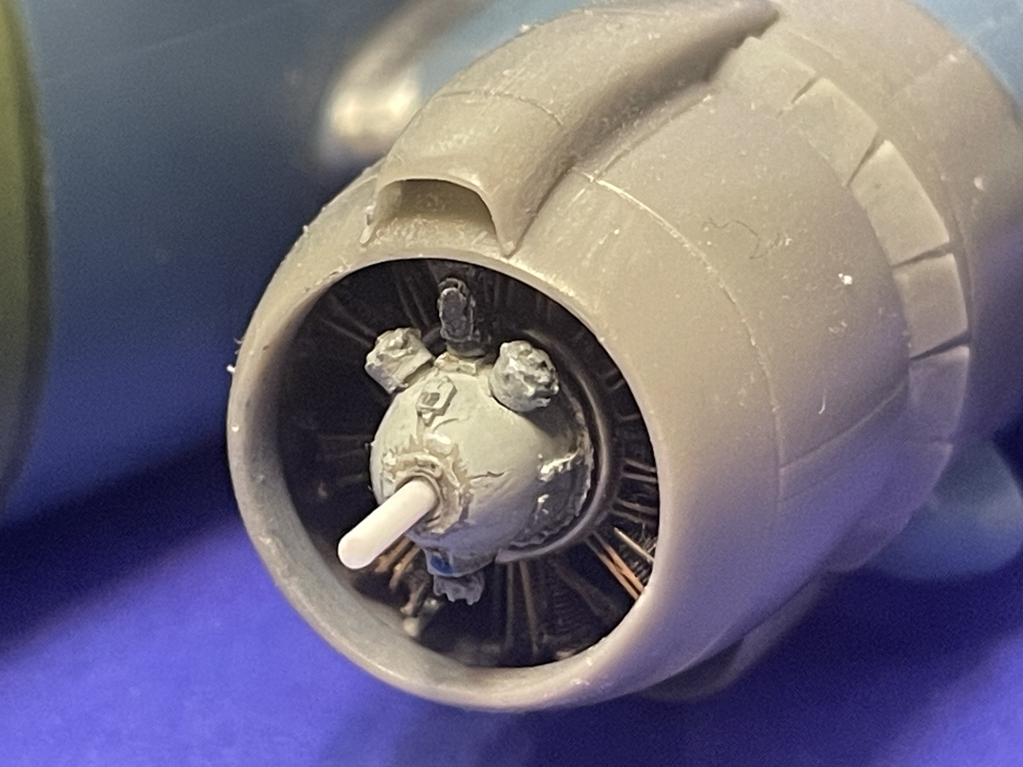
Next came the exhaust shrouds. The kit parts were substantially modified with a routing bit in my motor tool, removing the molded-in exhaust pipe. I got a little aggressive on the first shroud and unintentionally removed the sharp corner of one shroud, but I replaced it with a tiny triangle of styrene that I blended with CA and sanded it to shape. The exhaust pipe – made from brass tube – would be added later after the exhaust stain was applied.

Now came the time to add the wings. The fit was disappointing. I used CA gel to give me some time to adjust the alignment of the wings, matching them to the bases of the vertical tails. This left me with some gaps to fill on the top side of the wing roots, which I filled with .005 styrene strips and CA. I masked off the windows to protect them during sanding, then went at the wing roots with sandpaper of various grits.
This took a while – the details on the trailing edge and the contour of the thick wing made sanding an arduous affair. One trick that was incredibly helpful was the use of a silver Sharpie pen – after each sanding session, I would draw across the seam and the silver ink would show off any pits or imperfections that still required attention. After a week’s work, the seams, top and bottom, were eliminated. I re-scribed the lost lines on the wing and fuselage.

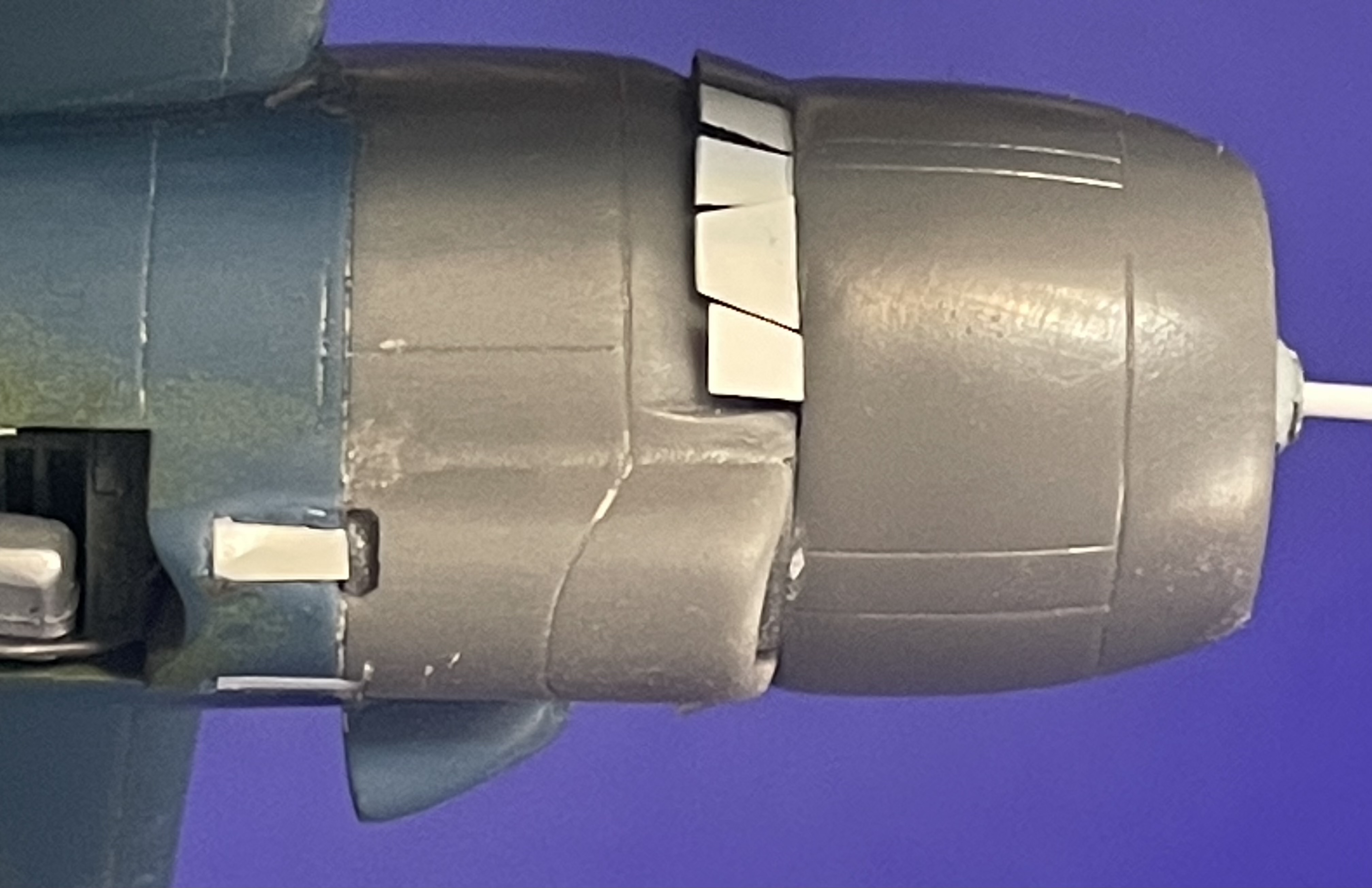
The engine cowlings from Plus Model still needed their upper scoop fronts added. The main part of the scoop is on the cowling; this part extends on to the nacelle for a seamless rear section. The front of the scoops are hollowed out and about 3/16 of an inch in depth, contoured to fit the front of the cowlings perfectly. Clean up was tricky, only because they’re so small; a razor saw removed them from the pour plug and fine sandpaper perfected the rear edges. Using gap-filling CA glue, I added the scoops and blended them with a fine sanding stick. I did this three or four times to eliminate any steps between front or back, or any imperfections at the base of the scoops’ sides. The silver Sharpie came in handy again here.
Now came the part of the build I was truly nervous about – the canopy glazing. The kit part was quite thick, so I planned on using a vacuformed Falcon replacement. That would be tricky enough. However, the PV-1 had a lot of gear mounted on the inside of the canopy – the torpedo sight, the compass, a map lamp and a second red lamp, and plenty of wiring to make it all work. There was also a chronometer on the top of the instrument panel and the motors for the windshield wipers. Installing these details without wrecking the canopy – and then installing the canopy without wrecking the details – would be a real challenge.
I started by getting the canopy ready. The Falcon canopy tells you to cut away the front of the fuselage ahead of the windshield, but this would have necessitated additional scratch-building of the instrument shroud. Instead, I trimmed carefully around the front of the windscreen with very sharp curved scissors. With straight scissors, I trimmed the back of the canopy so it fit snugly into the corners of the front of the cockpit. The fit was a little iffy – it was a bit long at the back and trimming was necessary.
My secret plan was to worry only about the front and rear fit of the canopy – I had numerous photos of PV-1s in Alaska with the cockpit side windows open. Opening them allowed me to skip fitting the lower sill – I could just add the windows later, after painting.
So, with the canopy cut out, I started cutting the side windows, using small, sharp scissors. The top edge cut went easily, but when I was cutting along the front frame I slipped and sliced into the clear panel at the top of the canopy. Argh!
I ordered another set of canopies and tried it again, this time using the technique suggested in the instructions of scoring along the canopy edges. This went fine until the blade slipped and put a fine scratch across the windscreen. Argh again!
After a brief tantrum, I thought I’d try to salvage the canopy by dipping it in Future and letting it dry. The result was promising – unless you look really hard you can’t see the scratch. I trimmed the canopy, carefully cut out the side panels, and achieved a good fit.
With great care, I added the wiring to the inside of the canopy frames with white glue, followed by scratch-built components for the navigator’s lamp, compass, torpedo sight and other things present in the photo of this plane taken from behind and between the pilot and co-pilot’s seat. This took a while to do without getting glue on the clear panels. Patience was critical here.

Next time: adding the canopy to the cockpit opening!
