
The Gannet AEW.3 build continues at a deliberate pace, with the holidays and various other things taking a bite out of my modeling time. I also paused to build this for my father-in-law’s N-gauge railroad layout as a Christmas gift:
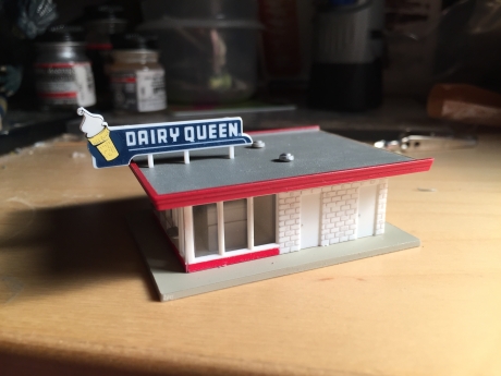
Who wants a teeny, tiny, itty-bitty, teeny-weenie, little Blizzard?
Then I was able to get back to work on the Gannet!
The floor and bulkheads were joined by the overhead duct in the Sword set to create a single radar observers’ compartment. To keep the compartment in place, I added lengths of styrene strip in one side of the fuselage. This gives a positive location for these parts and a way to ensure that they stay glued in place; nothing is more painful than having to crack open a model after a cockpit breaks loose inside a sealed fuselage!
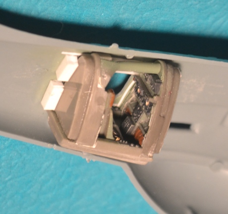
The completed radar observers’ compartment, held in place by styrene strip guides.
The extra overhead detail panels from the Sword kit fit poorly, and I thought I could add the detail easier on my own, anyway. The extra detailing in the radar observers’ compartment was accomplished fairly quickly, because I did something I rarely do: I stopped to figure out what would actually be visible. Although I had some good photos to work from, they were taken of an aircraft with the seats and much of the radar equipment removed. Put the seats back in, and you can’t see a lot of the detail. I added some structure from styrene strip and rod, made a couple of small black boxes from styrene card and Reheat photoetched instrument faces, and gave it all a wash to pop out the detail. The final touches were the emergency egress handles above the hatch openings; these were made from bits of styrene painted yellow and glued in place. The black stripes were drawn on with a .005mm Rapidograph pen.
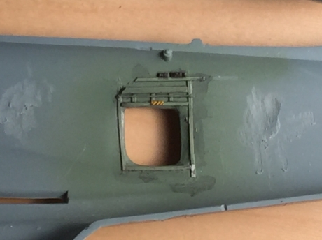
Let side of fuselage, with extra detail…
…And the right side. Note the small emergency egress handle above the door.
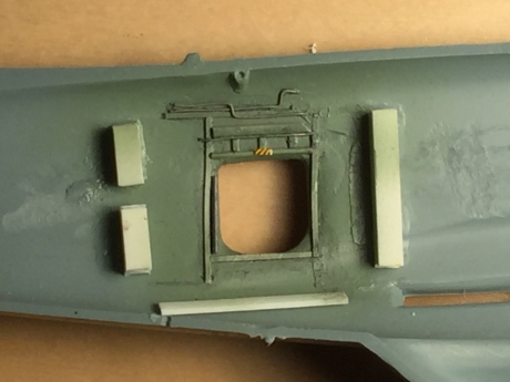
The next item of interest was the nose gear bay roof. The kit provides a good approximation of the basics, but omits the jungle of hydraulic and electrical wires so typical of 1950s wheel wells. Using photos, a copious amount of fine solder of three sizes, styrene bits and even a piece of stiff steel wire here and there, I added additional detail.
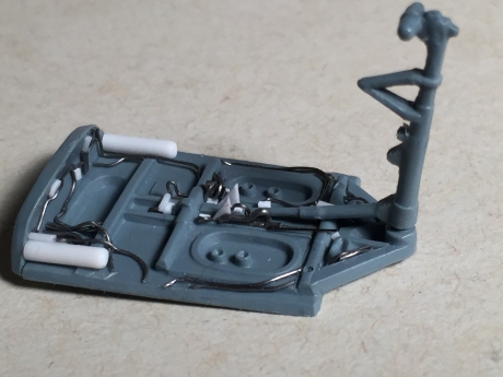
The strut was set in place to make sure my added detail didn’t make fitting the strut impossible later.
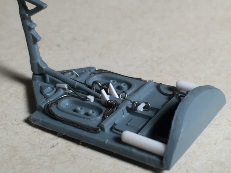
Detail in the form of hydraulic lines added to the nose gear bay.
Then, the whole thing was painted, given a wash and dry-brushed. And it looked great, except for the fact that I painted it the wrong color (interior gray-green). I painted over my work in the correct medium gray color and repeated the wash/dry-brushing routine. A bit of detail painting followed, and the nose wheel compartment was complete and ready to add to the model.
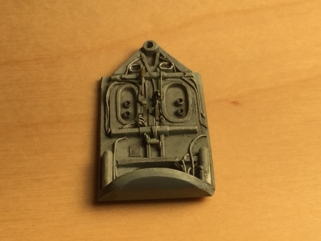
Why do they call it a wash? It only makes the parts look dirtier! I mean, come on!
At this point, a person not suffering from AMS would glue the interior parts in, join the fuselage halves, and get on with it. Not me! Next steps (pun intended) are the boarding ladder compartment and opening up the intakes in the nose (and creating a new compressor section for the Double Mamba engine to go behind it). Stay tuned for more gruesome details!
Leave a comment
No comments yet.

Leave a comment