
The Gannet’s progress has been slow, but deliberate. When we left off, I said I was going to open the boarding ladder, which Sword outlines quite nicely on the right side of the fuselage. I almost considered not cutting it out, because it impinged on the nose wheel well, but I then realized I could simply put a piece of .005 styrene over the right upper wall of the well and it would be just fine.
Of course, I then had to cut a slit in the side of the model that was 7/10ths of an inch long and 1/32 of an inch wide. As I did with the radar observer’s compartment doors, I chain drilled the ladder opening. The difference here was I had to drill every one of the holes in a near-perfect line. My fear was that I’d end up with an overly-wide opening, which would have looked cartoonish. Instead, when I cleaned up the opening with a No. 11 blade and some sandpaper, it looked just fine. The .005 styrene was added and the bay was airbrushed red; the interior of the wheel bay was painted gray. Mission accomplished!
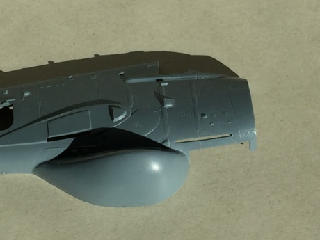
After chain-drilling, gentle carving and a bit of sanding, the ladder compartment is opened…
And, just like that, the back of the ladder compartment is closed, with .005 styrene.
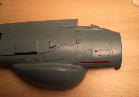
A little red paint finished off the ladder compartment.
Next, I opened up all the intakes in the nose. There are six of them – and the nose piece is very, very thick. The lower intakes are perfectly round, so it was a simple matter of drilling them out. Photos showed these intakes had screens inside of them; I struggled to find the right parts to replicate this until I stumbled across some 1:700 modern destroyer helicopter deck safety nets, which were perfect solutions.
The main intakes took a lot of work with a motor tool to open up, followed by plenty of careful cleanup with a No.11 blade and sandpaper. Getting the shapes of the openings the same was critical; that meant the first intake went really easily and the second one took a half hour to match up. The same went for the upper intakes.
Oh, cutting this open was fun.
Now I had to start thinking strategically. This model was going to be a tail-sitter for sure with the resin radar observer’s position well back of the main gear. To offset that, I added some pieces of thick styrene strip to the top of the nose wheel bay to function as a dam of sorts, then loaded in about 14 grams of split shot lead fishing weights, all secured with white glue. Another piece of styrene blocked it all in place.
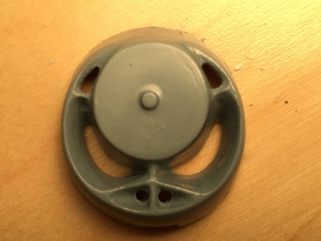
Then, I made the turbine faces for the Double Mamba engine. This was fairly simple. First, I made a backing plate that fit the fuselage; this would go right against the styrene strip at the front of the weight dam. Next, I added two quarter-inch sections of 7/32nds styrene tubing, gluing in place so that they were directly behind the inside walls of the intakes in relation to the nose piece. Turbine detail was added with half-round styrene strip; after it was glued into place, the excess was trimmed away.
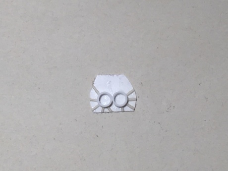
Simple but effective (and completed in less than an hour at the Fremont Hornets’ buildfest).
I painted this black, in keeping with photos, and lightly drybrushed my turbine blades. The goal here was not to replicate the entirety of the duct but to give a suggestion of something inside the nose, and this worked well.
Next, I joined the fuselage halves. The fit was not great, but I worked in sections to close it up. Sanding took a toll on some detail; most of it I could rescribe with my UM scribing tool, but the big reinforcement bands on the fuselage had to be replaced with strips of .005 styrene. Some small antenna detail was lost on the bottom, but this could be replaced during final construction.

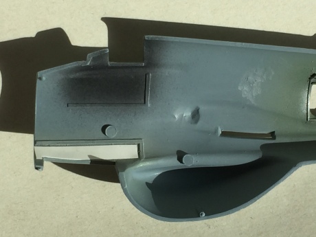
All closed up and (mostly) rescribed.
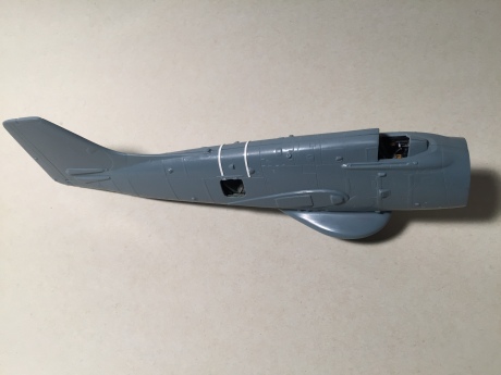
Note the two white strips – detail lost in sanding was replaced with .005 styrene strips.
Then, I added the turbine section. It fit neatly, and it blanked off the nose weight just behind it.
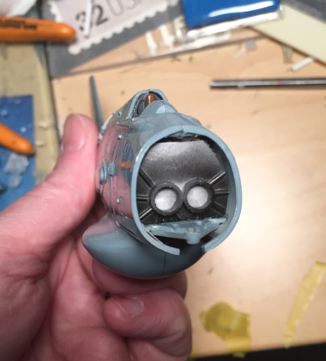
Peek a boo! The turbine section in its new home.
I painted the nose piece sky; this way, after it was added, I wouldn’t have to mask the black turbine section inside it during final painting. It also presented somewhat of a sloppy fit. It went on, but I had to do some significant sanding to get rid of seams and steps. That was followed by some tough rescribing of the fasteners on the nose, which I accomplished with Dymo tape and an old Verlinden scribing template. The rest of the nose detail was also added back in.
Whew! I now have a heavy but completely rescribed fuselage that’s ready for its wings. I’m going to pause, however, to work on another great 1950s design, the F-106 Delta Dart. More from the Gannet when the Delta Dart reaches the same stage the as this build!
Leave a comment
No comments yet.

Leave a comment